
Urgent Call?
+91-7453000063
Email Us
sales@acpvalves.in
+91-7453000063
sales@acpvalves.in
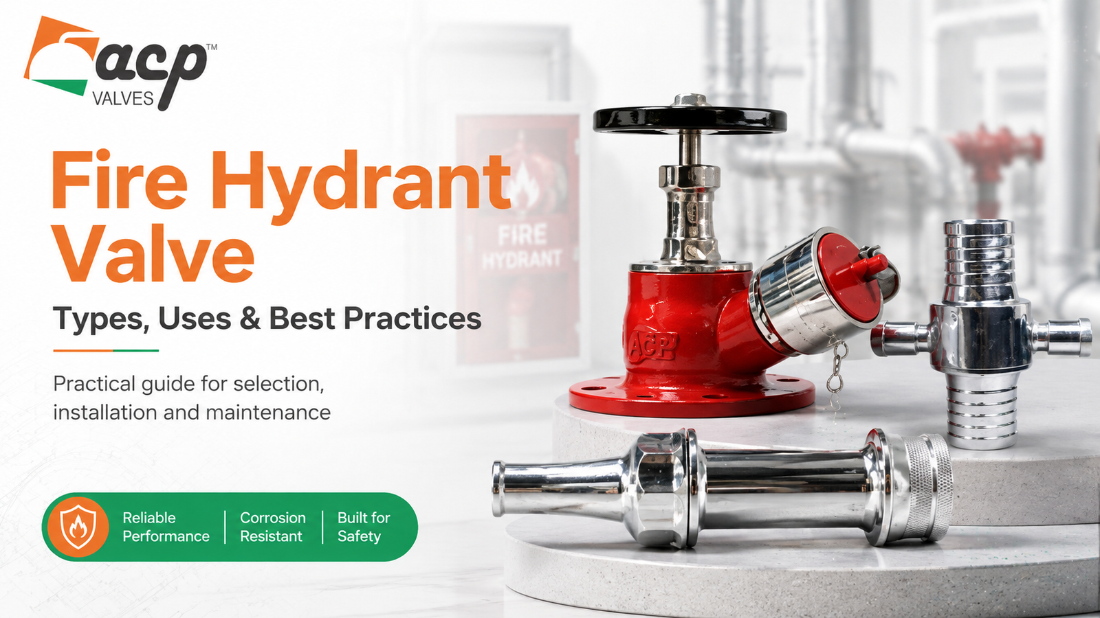
Fire hydrant valves may remain unused for long periods, but when a fire-water system is required they must provide dependable access to the pressurised water available in the network.
A fire hydrant valve is a manually operated outlet valve used in fire-protection systems. It allows firefighting personnel to connect suitable hose equipment and control the flow of water from the fire-water pipeline.
Selecting the correct valve involves more than matching a nominal pipe size. Engineers, contractors and buyers also need to consider valve type, pressure, materials, inlet and outlet connections, installation location, testing, maintenance and the requirements of the overall fire-protection system.
Quick answer: Common fire hydrant valve types include single-headed and double-headed configurations. Typical parts include the valve body, bonnet, spindle or stem, handwheel, seat, closing element, inlet connection, outlet coupling, packing and seals. The correct configuration depends on the fire-water system, installation location, pressure and project specification.
A fire hydrant valve is a manually operated valve installed at an accessible outlet of a pressurised fire-water network. Under normal conditions the valve remains closed.
When firefighting water is required, the valve is opened so that water from the fire-water pipeline can pass through the outlet to a connected hose or other suitable firefighting equipment.
In simple terms, the valve provides a controlled connection between the permanent fire-water system and the equipment used to deliver water during an emergency.
Because the valve forms part of a safety-critical system, its condition, accessibility and compatibility with the rest of the installation are important even when it is not used regularly.
The basic working principle of a hydrant valve is straightforward.
When the operator turns the handwheel, the stem or spindle moves the internal closing element away from the valve seat. This creates an open flow path between the fire-water pipeline and the valve outlet.
Pressurised water can then flow through the outlet to the connected firefighting equipment. Turning the handwheel in the opposite direction moves the closing element back toward the seat and stops the flow.
Although the operating principle is simple, reliable performance depends on suitable materials, accurate seating surfaces, sound manufacturing, correct installation and periodic inspection.
The exact construction can vary between manufacturers and configurations, but most designs contain several common components.
| Fire Hydrant Valve Part | Function |
|---|---|
| Valve Body | Main pressure-containing component that forms the water flow passage. |
| Bonnet | Encloses and supports the upper operating components of the valve. |
| Stem or Spindle | Transfers movement from the handwheel to the internal closing element. |
| Handwheel | Allows the operator to manually open or close the valve. |
| Seat | Provides the sealing surface against which the closing element rests. |
| Disc or Closing Element | Controls the water flow by moving toward or away from the seat. |
| Inlet Connection | Connects the valve to the pressurised fire-water pipeline. |
| Outlet and Coupling | Provides the connection point for the appropriate hose or firefighting equipment. |
| Packing and Seals | Help limit leakage around moving or joined components. |
The valve body contains the pressurised water and provides the main internal flow passage. Its material and construction need to suit the required pressure, environment and fire-water service.
The bonnet forms the upper enclosure of the valve and supports parts of the operating mechanism.
The stem or spindle transfers the rotational movement of the handwheel to the internal closing element.
The handwheel provides manual control. It should remain accessible so that the valve can be operated when required.
The seat provides the sealing surface used to stop water flow when the valve is closed.
The internal closing element moves relative to the seat as the valve is opened or closed.
The inlet connects the hydrant valve to the fire-water pipework. Its size and connection arrangement need to match the system specification.
The outlet provides the connection for firefighting equipment. Buyers should verify the required outlet size and coupling arrangement rather than assuming that all hydrant valves use the same connection.
Packing and sealing components help control leakage while allowing the operating parts of the valve to move.
Fire hydrant valve types are often distinguished by the number of outlets and the configuration required by the installation.
A single-headed hydrant valve provides one firefighting outlet. This configuration may be used where one hose connection is required at the hydrant point.
Selection should still consider pressure, inlet arrangement, outlet size, coupling, material and project requirements.
A double-headed hydrant valve provides two outlets from the hydrant point. This can allow two hose connections where the fire-protection design requires them.
The presence of two outlets does not remove the need to check available flow, pressure and the design of the wider fire-water network.
Hydrant valves may be installed within buildings, industrial facilities or external fire-water networks depending on the system design.
The installation environment can influence accessibility, protection from damage, material selection and the arrangement of the inlet and outlet connections.
Fire hydrant valves and landing valves perform closely related functions because both provide controlled access to water from a fire-protection system.
| Point | Fire Hydrant Valve | Landing Valve |
|---|---|---|
| Main role | Provides a controlled outlet from a pressurised fire-water network | Provides an accessible outlet from a building riser or fire-water network |
| Typical location | Industrial sites, buildings and external hydrant networks | Often associated with building and riser installations |
| Operation | Normally manually operated | Normally manually operated |
| Selection depends on | Pressure, configuration, materials, connection and project requirements | Pressure, connection, location and project requirements |
The distinction is not always absolute because terminology can vary between project specifications and regions. The actual valve construction, connection arrangement, required pressure and applicable specification should therefore take priority over the terminology alone.
Where a project specifically requires a landing hydrant valve product, buyers can review the ACP landing hydrant valve range separately for product-specific information.
Hydrant valves are used wherever a pressurised fire-water system needs accessible outlets for firefighting operations.
The correct arrangement depends on the overall fire-protection design rather than the building or industry name alone.
A reliable selection process starts with the system requirement and then checks the valve configuration against the project specification.
Identify where the valve will be installed and how firefighting personnel are expected to access and operate it.
Determine whether the project requires a single-headed, double-headed or another specified configuration.
Confirm the required inlet size, outlet size, connection type, orientation and coupling arrangement.
The selected valve should be suitable for the operating and test conditions specified for the fire-water system.
Do not select a valve based on nominal size alone.
Body and internal materials should suit the service conditions, installation environment and project specification.
Environmental exposure, corrosion and maintenance conditions may influence material selection.
Verify whether the project requires threaded, flanged or another specified inlet arrangement and confirm the outlet coupling requirements.
Fire-protection projects may specify particular valve construction, testing or approval requirements. Buyers should confirm the applicable project specification before placing an order.
Before procurement, determine what technical documentation, test information, inspection records or certificates must be supplied with the valve.
| Check | What to Confirm |
|---|---|
| Valve type | Single-headed, double-headed or project-specific configuration |
| Installation | Internal, external, building, industrial or other specified location |
| Inlet | Required size and connection arrangement |
| Outlet | Required outlet and coupling configuration |
| Pressure | Working and test conditions |
| Materials | Body, trim and sealing materials |
| Specification | Applicable project or fire-protection requirements |
| Documentation | Testing, inspection and certification requirements |
| Accessibility | Clear access for operation, hose connection and inspection |
Even a correctly selected hydrant valve can become difficult to use if it is installed poorly.
The project specification and approved installation procedure should always take priority over general guidance.
Hydrant valves may remain idle for long periods, which makes periodic inspection especially important.
A maintenance programme may include checking:
Inspection and testing frequency should follow the applicable fire-protection requirements, plant procedures and manufacturer recommendations.
This may indicate lack of movement over a long period, corrosion, damaged operating components, contamination or another mechanical problem.
Leakage around the operating stem may be associated with worn or incorrectly adjusted packing or sealing components.
Possible causes can include contamination or damage around the seating surfaces, wear of the closing components or mechanical problems in the operating mechanism.
A damaged outlet or coupling can make hose connection difficult or unreliable. These components should therefore be included in routine inspection.
Equipment, stored material or later construction changes should not obstruct access to a fire hydrant valve.
Fire hydrant valve pricing can vary because apparently similar valves may differ substantially in construction and project requirements.
Important factors can include:
A technically incomplete quotation request can therefore produce misleading price comparisons.
Providing this information helps a supplier evaluate the actual requirement rather than recommend a valve only from its nominal size.
A hydrant valve should not be viewed as an isolated component. Its ability to provide useful firefighting water also depends on the condition and design of the wider fire-water network.
Pipe sizing, available pressure, pumps, water supply, layout, accessibility and firefighting equipment all influence the performance of the complete system.
The most reliable procurement approach therefore begins with the approved fire-protection design and project specification, followed by the valve configuration, pressure, materials, connections, documentation and inspection requirements.
A fire hydrant valve is a manually operated outlet valve that provides controlled access to water from a pressurised fire-water system for firefighting use.
Turning the handwheel moves the internal closing element away from its seat, allowing water from the pressurised fire-water line to flow through the outlet. Closing the valve returns the element toward the seat and stops the flow.
Common configurations include single-headed and double-headed hydrant valves. Designs can also vary by inlet connection, outlet orientation, coupling arrangement and installation requirement.
Typical fire hydrant valve parts include the valve body, bonnet, stem or spindle, handwheel, seat, closing element, inlet connection, outlet or coupling, packing and seals.
Both provide controlled access to a fire-water supply. Landing valves are commonly associated with building risers, while fire hydrant valve terminology may also cover industrial or outdoor fire-water outlets. The project specification should determine the actual valve required.
They are used in factories, warehouses, industrial plants, commercial buildings, high-rise buildings and external fire-water networks where accessible firefighting water outlets are required.
A single-headed hydrant valve provides one firefighting outlet from the fire-water network. Its exact size, connection, pressure and coupling arrangement depend on the project specification.
A double-headed hydrant valve provides two outlets at the hydrant point where the fire-protection design requires two hose connections.
No. Pipe size is only one consideration. Pressure, valve configuration, connections, material, outlet arrangement, system requirements and applicable specifications also need to be checked.
Provide the required valve configuration, inlet and outlet sizes, pressure conditions, materials, applicable project specification, coupling requirements, quantity, testing requirements and required documentation.
A fire hydrant valve performs a simple but critical role by providing controlled access to water from a pressurised fire-protection system.
Understanding the main fire hydrant valve types, parts and working principle helps engineers and buyers evaluate a valve more accurately. Selection should consider the complete installation rather than nominal size alone, including configuration, pressure, materials, connections, accessibility, testing and project requirements.
A correctly specified valve that is properly installed and periodically inspected is much more likely to operate as intended when the fire-water system is actually needed.




Copyright © 2022. All rights reserved.ACP VALVES
Crafted With ❤️ By Digicircal – Web Designing, Digital Marketing & Branding Company