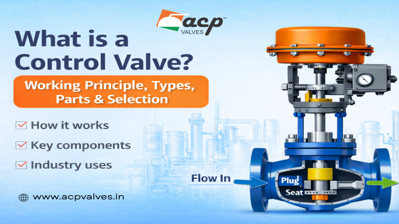
A control valve is used to regulate flow, pressure, temperature or liquid level in an industrial process system. Unlike a basic isolation valve that mainly opens or closes a pipeline, a control valve continuously adjusts its opening according to process demand.
The main control valve parts include the valve body, bonnet, trim, stem or shaft, actuator, positioner, packing and gaskets. Different control valve types are available for different process conditions, including globe, ball, butterfly, diaphragm and three-way control valves.
Control valves are widely used in steam, water, oil, gas, chemical and process systems where stable operation and accurate flow control are important. Correct selection depends on the process media, pressure, temperature, flow rate, pressure drop, required control characteristics, actuator type and maintenance requirements.
Understanding control valve parts, types and working principle helps engineers, maintenance teams and industrial buyers compare valve designs and select a suitable solution for the actual process conditions.
What Is a Control Valve?
A control valve is an industrial valve designed to regulate the movement of fluid through a pipeline. It changes its opening based on a signal received from a controller, positioner or automation system.
For example, when a process requires more flow, the control system can command the valve to open further. When the required flow decreases, the valve moves toward the closed position.
This continuous adjustment helps maintain the required process condition instead of simply switching the pipeline between fully open and fully closed.
What Are the Main Parts of a Control Valve?
The main control valve parts work together to control fluid movement accurately and reliably. Although construction varies according to valve design, application and actuator arrangement, the major parts generally include the valve body, bonnet, trim, stem or shaft, actuator, positioner, packing and gaskets.
- Valve Body: Contains the main fluid passage and connects the valve to the pipeline.
- Bonnet: Supports the upper valve components, including the stem and packing arrangement.
- Valve Trim: Includes internal components that directly control the flow of fluid.
- Stem or Shaft: Transfers actuator movement to the internal flow-control element.
- Actuator: Generates the force or torque required to operate the valve.
- Positioner: Helps position the valve according to the required control signal.
- Packing and Gaskets: Provide sealing at the stem and valve joints.
Main Control Valve Parts and Their Functions
1. Valve Body
The valve body contains the internal flow path and connects the control valve to the pipeline. Body material should be selected according to pressure, temperature, process media and corrosion conditions.
2. Bonnet
The bonnet covers the upper section of the valve body and supports components such as the stem and packing assembly. Its construction should be suitable for the process temperature, pressure and service conditions.
3. Valve Trim
Valve trim refers to the internal components that directly interact with and regulate fluid flow. Depending on the type of control valve, the trim may include a plug, seat, disc, cage or other flow-control elements.
Trim design has an important influence on flow characteristics, shutoff performance and the way the valve responds to changes in position.
4. Stem or Shaft
The stem or shaft connects the actuator movement to the internal valve element. Linear valves generally use a stem, while rotary valves typically use a shaft to rotate a ball or disc.
5. Actuator
The actuator supplies the force or torque required to move the control valve. Depending on the system, actuators may be pneumatic, electric or another suitable industrial design.
The actuator should be selected according to valve size, required operating force or torque, control system and fail-safe requirements.
6. Positioner
A valve positioner helps ensure that the actual valve position corresponds to the control signal. It can improve positioning accuracy when precise process control is required.
7. Packing and Gaskets
Packing provides sealing around the valve stem, while gaskets seal joints between valve components. Correct material selection is important because these components may be exposed to pressure, temperature and aggressive process media.
Control Valve Components and Their Function
The different control valve components operate as one system. The body provides the pressure-containing flow path, the trim regulates fluid movement, the stem or shaft transfers motion, the actuator generates movement and the positioner helps achieve the required valve opening.
Packing and gaskets support sealing performance. Understanding these components is useful when selecting a valve, diagnosing performance problems or planning maintenance.
Control Valve Working Principle – How Does It Work?
The control valve working principle is based on changing the available flow area inside the valve. A sensor measures a process condition such as flow, pressure, temperature or liquid level. The controller compares that value with the required set point and sends a signal to the actuator.
The actuator then moves the valve stem or shaft. This changes the position of the plug, ball, disc or another internal control element and increases or decreases the available flow area.
Basic Control Valve Working Sequence
- A sensor measures the process condition.
- The process controller compares the measured value with the required set point.
- The controller sends a control signal.
- The actuator receives the signal and moves the valve stem or shaft.
- The valve trim, ball or disc changes position.
- The available flow area increases or decreases.
- The process condition moves toward the required set point.
Depending on the automation system, the signal may be pneumatic, electric or another supported industrial control signal.
Types of Control Valve and Their Applications
There are several types of control valve, and each design has different operating characteristics. The correct choice depends on factors such as required flow control, pressure drop, pipe size, process media, temperature and operating conditions.
1. Globe Control Valve
A globe control valve uses linear movement of a plug relative to a seat to regulate flow. Globe-style valves are commonly considered where accurate throttling and controlled adjustment are important.
Their trim can be designed for different flow characteristics, making them suitable for many industrial process-control applications.
2. Ball Control Valve
A ball control valve uses a rotating ball to regulate fluid flow. Rotary movement allows relatively quick operation, while different ball and port designs can provide different control characteristics.
Ball valves may be considered for selected liquid, gas and industrial process applications depending on the required control performance.
3. Butterfly Control Valve
A butterfly control valve uses a rotating disc installed in the flow path. Its compact construction can be useful for larger pipeline sizes where installation space and weight are important considerations.
Butterfly valves are commonly used in water and selected industrial fluid-handling systems.
4. Diaphragm Control Valve
A diaphragm control valve uses a flexible diaphragm as part of the operating and sealing arrangement. Depending on the design and material compatibility, diaphragm valves can be considered for selected water, chemical and process applications.
5. Three-Way Control Valve
A three-way control valve contains three flow connections and is generally used for mixing or diverting process streams.
For example, a three-way valve may combine two incoming streams into one outlet or divert one incoming stream between two different flow paths.
Control Valve Types Comparison
| Control Valve Type | Operation | Key Characteristic | Typical Application |
|---|---|---|---|
| Globe Control Valve | Linear | Accurate throttling | Steam and process control |
| Ball Control Valve | Rotary | Fast rotary operation | Liquid and gas flow control |
| Butterfly Control Valve | Rotary | Compact construction | Water and larger pipelines |
| Diaphragm Control Valve | Linear | Diaphragm-based operation | Selected chemical and water systems |
| Three-Way Control Valve | Linear or Rotary | Mixing or diverting | Process and temperature-control systems |
Control Valve Flow Characteristics
Flow characteristic describes the relationship between valve travel and flow through the valve under defined conditions. Understanding this relationship is important when matching the valve response to process requirements.
Linear Characteristic
With a linear characteristic, equal increments of valve travel produce approximately equal increments of flow under the defined test conditions.
Equal Percentage Characteristic
With an equal-percentage characteristic, equal increments in valve travel produce approximately equal percentage changes in the existing flow coefficient. This characteristic can be useful where the operating range varies significantly.
Quick Opening Characteristic
A quick-opening characteristic produces a relatively large increase in flow during the initial portion of valve travel. It is generally more suitable for applications requiring rapid flow increase than for precise throttling across the full travel range.
Where Are Control Valves Used?
Control valves are used wherever a process variable needs automatic regulation. Typical industrial applications include:
- Steam and boiler systems
- Water-treatment systems
- Oil and gas pipelines
- Chemical processing
- Power plants
- Heating and cooling systems
- Food and beverage processing
- Pharmaceutical processing
- Industrial utility systems
- Process manufacturing plants
The exact valve construction, material and actuator arrangement should always be matched to the actual service conditions.
How to Select the Right Control Valve
Control valve selection should not be based only on pipeline diameter. A valve that physically fits the pipe may still provide poor control if its capacity, trim, actuator or material is unsuitable for the process.
1. Identify the Process Media
Determine whether the valve will handle water, steam, oil, gas, chemicals or another process fluid. Media characteristics affect body, trim, seat, seal and packing material selection.
2. Check Flow Requirements
Determine normal, minimum and maximum flow conditions whenever possible. A control valve should operate effectively across the expected process range.
3. Determine Pressure Conditions
Check upstream pressure, downstream pressure and expected pressure drop across the valve. These values are important for valve sizing and performance assessment.
4. Check Process Temperature
Temperature affects the suitability of body materials, seats, packing, gaskets and other valve components.
5. Select the Appropriate Valve Type
Choose between globe, ball, butterfly, diaphragm or another valve design according to the required control characteristics and process conditions.
6. Consider Flow Characteristics
The required process response can influence whether linear, equal-percentage or another suitable trim characteristic should be considered.
7. Select the Actuator
The actuator must provide sufficient force or torque to move the valve reliably under operating conditions.
8. Consider Fail Position
Depending on process safety requirements, the control valve may need to move to a defined position if power or control energy is lost. The required fail action should be established during valve and actuator selection.
Control Valve Selection Checklist
Before selecting a control valve, collect the following process information:
- Process fluid or media
- Minimum, normal and maximum flow rate
- Upstream pressure
- Downstream pressure
- Available pressure drop
- Operating and design temperature
- Pipeline size
- Required body and trim materials
- Required valve type
- Required flow characteristic
- Actuator type
- Control signal
- Required fail position
- Shutoff requirements
- Maintenance and accessibility requirements
Providing accurate process data makes it easier to select and size the valve correctly.
Why Control Valve Sizing Matters
Control valve sizing determines whether the valve has suitable capacity for the required flow and pressure conditions. Selecting a valve only according to pipeline size can lead to poor control performance.
A correctly selected valve should have enough capacity for the maximum required flow while still providing useful control across normal and lower operating conditions.
Common Control Valve Sizing Mistakes
Oversizing the Valve
An oversized valve may operate through only a small portion of its available travel during normal conditions. This can make stable control more difficult and may contribute to unnecessary cycling or poor response.
Undersizing the Valve
An undersized valve may not provide sufficient capacity at maximum process demand and can create excessive pressure loss.
Ignoring Pressure Drop
Pressure drop across the valve is an important sizing parameter. Using only pipe diameter and flow rate without considering pressure conditions can result in incorrect selection.
Ignoring Process Range
Control valves frequently operate at several different flow conditions. Minimum, normal and maximum operating requirements should therefore be considered during selection.
Control Valve Maintenance Checklist
Routine inspection and preventive maintenance can help maintain reliable control-valve operation. Maintenance requirements depend on valve type, process conditions and operating frequency.
- Inspect the valve body for visible leakage or corrosion.
- Check packing areas for leakage.
- Inspect the actuator and its connections.
- Check positioner operation where fitted.
- Observe valve response during operation.
- Inspect internal trim during scheduled shutdowns where appropriate.
- Check seats and sealing surfaces for wear.
- Inspect pneumatic or electrical connections.
- Check for abnormal vibration or noise.
- Follow the manufacturer’s maintenance recommendations.
Common Control Valve Problems
Valve Hunting or Cycling
Repeated movement around the required position may be associated with sizing, tuning, friction, positioner performance or changing process conditions.
External Leakage
Leakage around the stem or body joints may indicate worn packing, damaged gaskets, loose joints or unsuitable sealing materials.
Internal Leakage
If the valve cannot achieve the required shutoff, the seat or other internal sealing components may be worn, damaged or obstructed.
Slow Valve Response
Slow response can be associated with actuator issues, inadequate air supply, friction, positioner problems or mechanical restrictions.
Noise or Vibration
Abnormal noise or vibration should be investigated because it may indicate unsuitable operating conditions, excessive pressure drop or other process and valve-selection issues.
Control Valve vs On-Off Valve
| Feature | Control Valve | On-Off Valve |
|---|---|---|
| Main Purpose | Regulates a process variable | Starts or stops flow |
| Typical Position | Can operate at intermediate positions | Mainly fully open or fully closed |
| Control | Modulating | On/off |
| Automation | Often works with controller and positioner | Generally simpler open/close control |
| Typical Use | Flow, pressure, temperature or level regulation | Pipeline isolation |
The main difference is therefore the purpose of the valve. An on-off valve primarily isolates flow, while a control valve continuously changes its position to regulate a process condition.
Why Control Valve Quality and Correct Selection Matter
A control valve is an active part of a process-control loop. Its performance can influence process stability, product consistency, system efficiency and maintenance requirements.
Correct selection requires more than choosing a valve with the same nominal size as the pipeline. Buyers and engineers should consider media compatibility, pressure, temperature, flow conditions, valve capacity, trim characteristics, actuator requirements and maintenance accessibility.
For industrial projects involving several valve categories, you can also review ACP Valves’ industrial valve products to compare available solutions for different pipeline requirements.
Why ACP Valves?
ACP Valves supports industrial pipeline applications with valves, boiler mounting products, fittings and related flow-control products. Valve selection can be evaluated according to media, pressure, temperature, pipeline size and operating requirements.
For buyers comparing valve solutions for steam, water, oil, gas and industrial process systems, evaluating the actual application data before final selection can help avoid sizing and compatibility problems.
For product requirements or technical discussions, visit the ACP Valves contact page or explore the complete valve product range.
Frequently Asked Questions About Control Valves
What are the main parts of a control valve?
The main parts of a control valve generally include the valve body, bonnet, trim, stem or shaft, actuator, positioner, packing and gaskets. The exact components depend on the valve design and application.
What are the different types of control valve?
Common types of control valve include globe control valves, ball control valves, butterfly control valves, diaphragm control valves and three-way control valves. Each type has different operating characteristics and suitable applications.
What is the working principle of a control valve?
The control valve working principle involves changing the available flow area inside the valve in response to a control signal. The actuator moves the valve stem or shaft, changing the position of the internal flow-control element and regulating the process.
What are the main control valve components?
The main control valve components include the body, bonnet, trim, stem or shaft, actuator, positioner, packing and sealing components. These parts work together to regulate fluid flow and maintain the required process condition.
Which control valve is commonly used for throttling?
Globe-style control valves are commonly considered for applications requiring accurate throttling. However, the correct valve should be selected according to process media, flow requirements, pressure drop, temperature and other operating conditions.
Why is control valve sizing important?
Correct control valve sizing helps ensure that the valve has sufficient capacity while maintaining useful control across the expected operating range. Oversizing or undersizing can contribute to poor control performance.
What does a control valve regulate?
A control valve can regulate process variables such as fluid flow, pressure, temperature or liquid level depending on the system and control-loop arrangement.
What is the difference between a control valve and an isolation valve?
A control valve changes its position continuously or incrementally to regulate a process variable. An isolation valve is primarily intended to fully open or close a flow path.
Final Thoughts
Understanding control valve parts, control valve types, control valve working principle and control valve components makes it easier to evaluate how a valve will perform in an industrial process.
The valve body, trim, actuator and positioner must work together correctly, but successful valve selection also depends on accurate process information. Flow rate, pressure drop, temperature, media compatibility, required flow characteristic and actuator requirements should all be considered before final selection.
For industrial applications, selecting the valve according to actual operating conditions rather than pipeline size alone can help achieve more stable control and more reliable long-term operation.
Need help selecting an industrial valve? Review the ACP Valves product range or contact ACP Valves with your media, pressure, temperature, flow and pipeline requirements.